Flow distribution and blade loading
Evaluate the velocity and pressure fields through the rotor to understand how flow interaction with the blade surfaces contributes to torque.
CFD CASE STUDY / TURBOMACHINERY
For Hayzel (United States), three-dimensional CFD was used to investigate internal flow behavior, identify sources of performance losses, and evaluate changes to rotor geometry.
The revised rotor achieved an 18% increase in predicted mechanical power compared with the initial design.
Three-dimensional CFD · Rotor design evaluation · Results are simulation predictions, not measured performance
01 / THE ENGINEERING CHALLENGE
The objective was to evaluate the aerodynamic performance of an existing axial impulse turbine and identify opportunities to improve its mechanical power output.
The investigation considered interactions between the inlet flow, rotating turbine blades and geometric features affecting pressure distribution, momentum transfer and rotor torque.
Inspect the geometry and flow fields →Evaluate the velocity and pressure fields through the rotor to understand how flow interaction with the blade surfaces contributes to torque.
Investigate geometric clearances and leakage pathways that can reduce momentum transfer to the rotor.
Identify changes to the rotor geometry and quantify their influence on predicted torque and mechanical power.
02 / CFD VISUALIZATION
Explore velocity structures, the equilibrium thermodynamic field and detailed computational mesh views. These are distinct engineering visualizations, not frames of a transient animation.
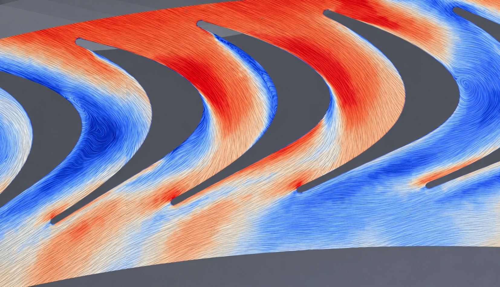
FLOW VISUALIZATION · VELOCITY STRUCTURECFD / FLOW STRUCTURE
A contrast-enhanced visualization highlights flow turning, local acceleration and complex flow structures through the rotor blade passages. This presentation image is not a quantitative velocity scale.
Visualization: contrast-enhanced image derived from supplied CFD imagery; use the underlying results, not image colors, for quantitative interpretation.
Use the figure buttons or ← / → when the viewer is focused. Enlarge figures to inspect the original mesh detail.
03 / NUMERICAL APPROACH
The model represented the rotor, surrounding flow passages and relevant geometric clearances. It was used to evaluate flow behavior and performance-loss mechanisms and to compare rotor configurations.
A pressure-dependent barotropic fluid model represented changes in thermodynamic properties across the turbine. The vapor-quality visualization is an equilibrium field inferred from this model, not a separately transported phase.
Pressure-dependent density ρ(p) · equilibrium mixture
A steady rotating reference frame and the k–ω SST turbulence model were used to calculate pressure and velocity fields, blade loading and integrated rotor torque.
3D RANS · rotating reference frame · torque integration
The mesh followed the turbine blade geometry and resolved relevant near-wall regions and leakage pathways. Numerical convergence and global mass conservation were checked.
≈26 million cells · local refinement · mass balance
04 / DESIGN EVALUATION
The initial analysis identified mechanisms contributing to performance losses. Based on this assessment, modifications were made to the rotor geometry.
The revised configuration was then evaluated using CFD to assess changes in flow distribution, blade loading, rotor torque and mechanical power.
The revised rotor geometry achieved an 18% increase in predicted mechanical power compared with the initial design under equivalent simulated operating conditions.
The comparative analysis provided a quantitative assessment of the geometry changes and supported the selection of the improved design.
CFD prediction at the evaluated operating conditions; not an experimentally measured improvement.05 / ENGINEERING OUTCOME
Detailed flow analysis linked rotor geometry, internal flow distribution, leakage effects and mechanical power output. The investigation supported a revised rotor configuration with improved predicted performance.
ENGINEERING SERVICES
From identifying flow losses to evaluating geometry modifications, CFD can support informed turbomachinery design decisions.